METHOD OF STATEMENT FOR BACKFILLING & COMPACTION WORK
PURPOSE The purpose of this Method Statement is to establish the procedures and controls to be applied during all backfilling and compaction works, including the selection of suitable fill material, placement in layers, moisture adjustment, compaction, inspection, testing, and preparation of the subgrade for ground slabs and external areas. This ensures that all backfilling and compaction works are executed in accordance with Project Specifications, approved drawings, and applicable standards, providing a stable and uniform foundation for subsequent construction activities
MACHINARIES
a. Surveying Instruments b. Compactor as per requirement c. Excavator / Loader for placing fill d. Water Tanker e. Electric Tamping Rammer
• Equipment’s to be used at the job site shall include, but not limited to the following:
Manpower and Equipment a. Construction Manager b. Project Civil Engineer c. Civil Construction Supervisor / Forman d. Surveyor e. Civil QC Inspector f. Safety Officer g. Operators for machineries h. Helpers
METHOD OF STATEMENT FOR BACK FILLING & COMPACTION WORK
1. Preparation
Excavations areas shall only be backfilled after permanent works are approved by the consultant.
Required machineries inspected before starting the work
2. Backfilling
Selected excavated material shall be used for backfilling where suitable.
If excavated material is unsuitable, approved imported material shall be used.
Complete installation of service ducts and pipework before placing fill and inspected by MEP Engineers If required
Backfill shall be brought to levels above grade to allow for anticipated settlement.
Backfill shall be sloped away from permanent structures for proper drainage.
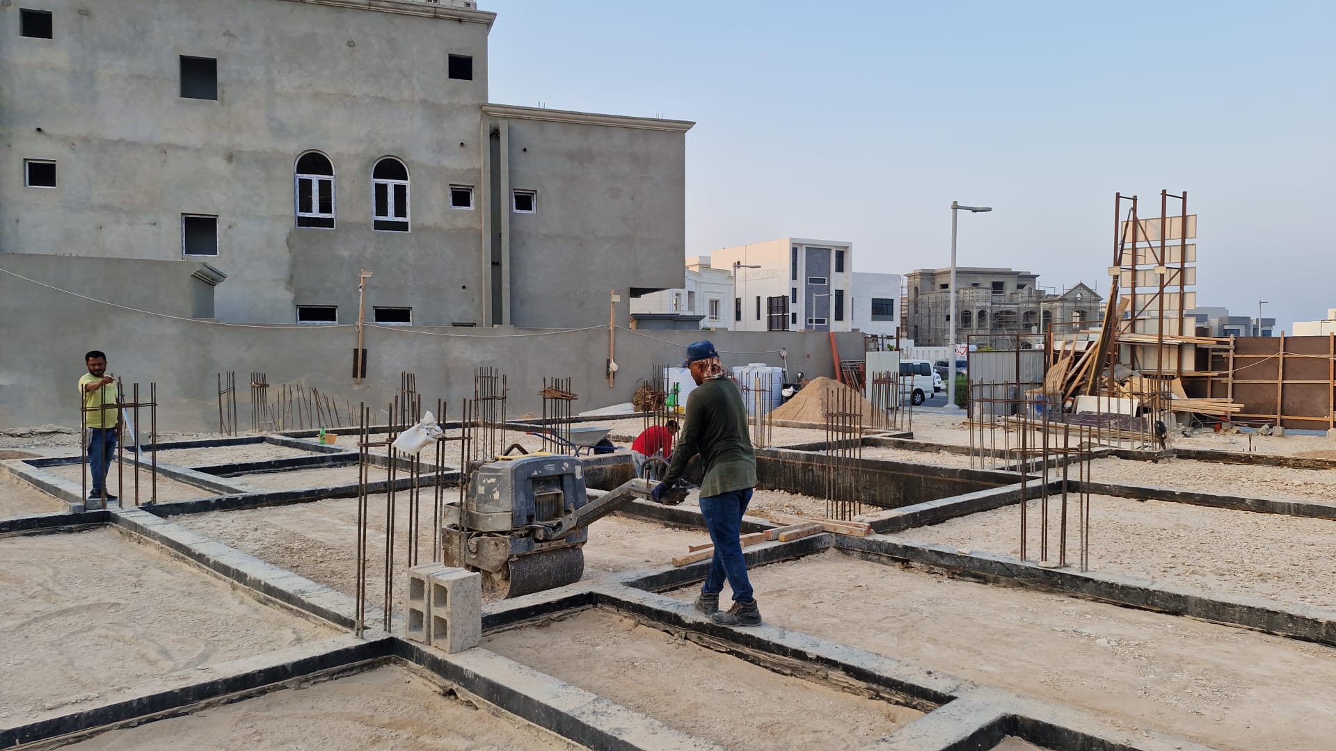
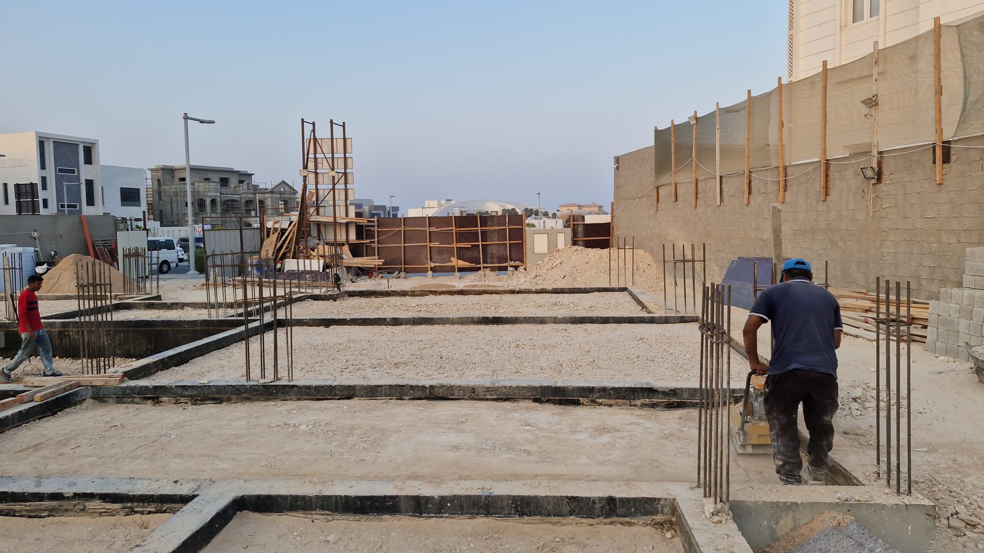
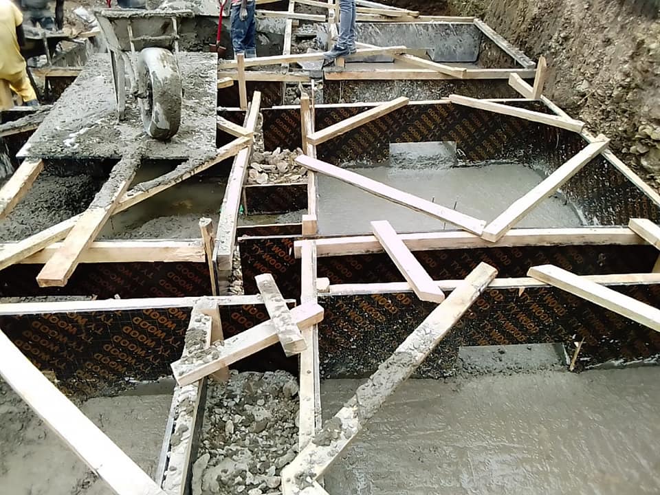
3. Placement and Compaction
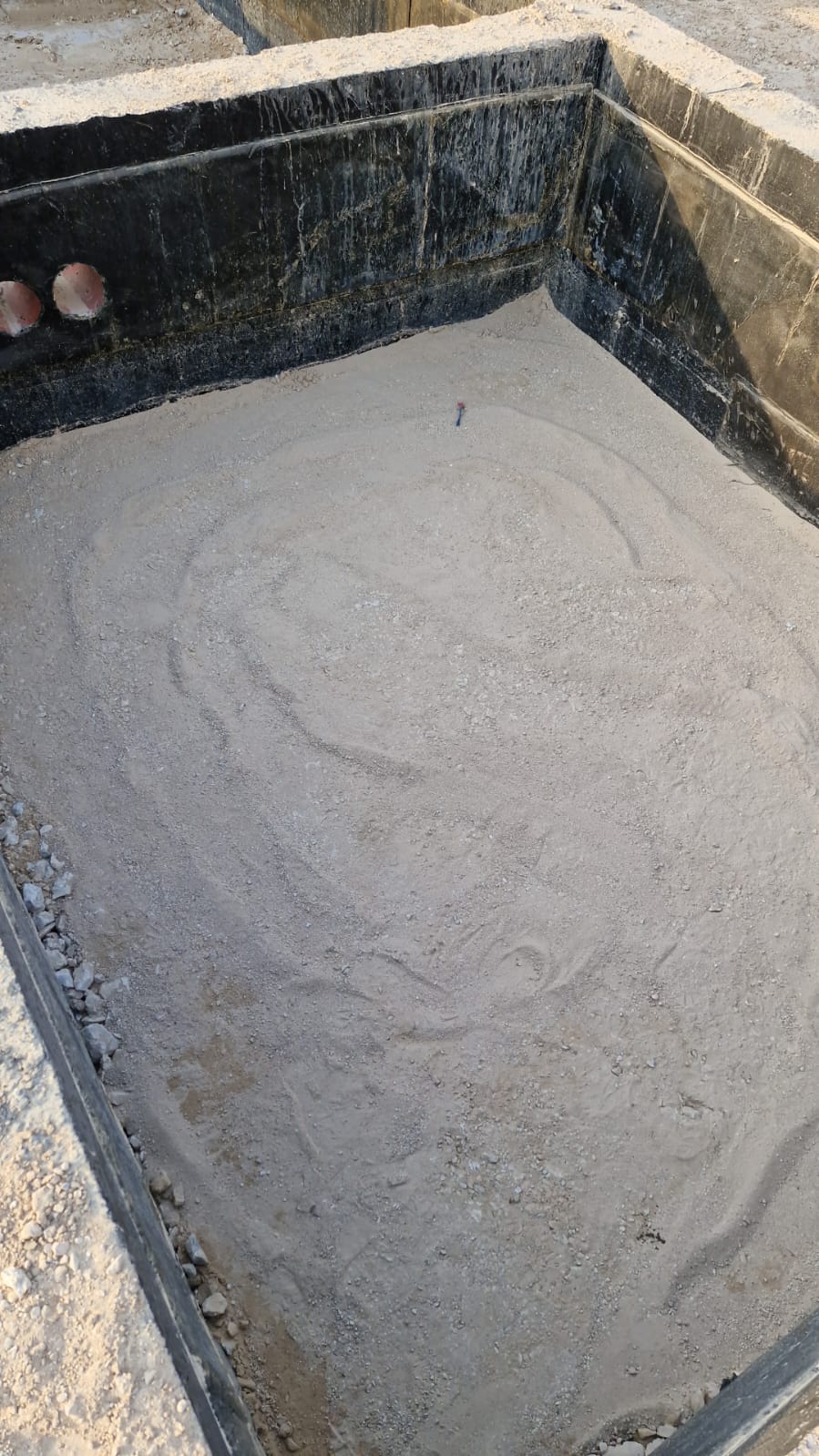
The material is to be placed in layers within the effective range of compaction of the plant provided that the maximum loose (uncompacted) thickness of each layer does not exceed 200 mm.
Adjust moisture content to ±3% of optimum moisture content.
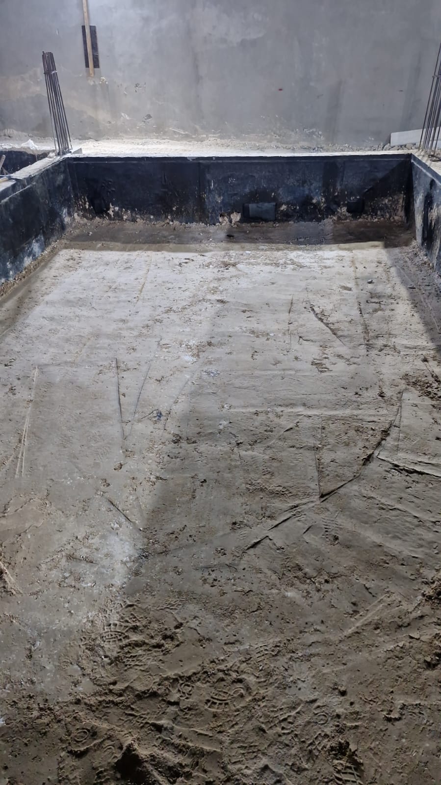
Compact each layer using approved compaction equipment until ≥ 95% maximum dry density is achieved.
Every layer is properly backfilled & Compacted as per specification
Compact each layer using suitable equipment until achieving the required density.
Repeat process until the final required level is reached.
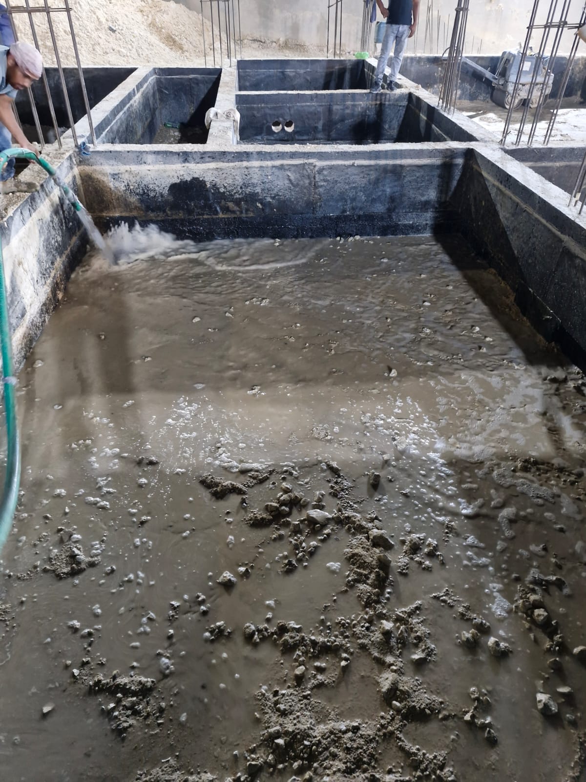
Portable water to be used while compaction, also Ensure that uniform moisture distribution throughout compaction.
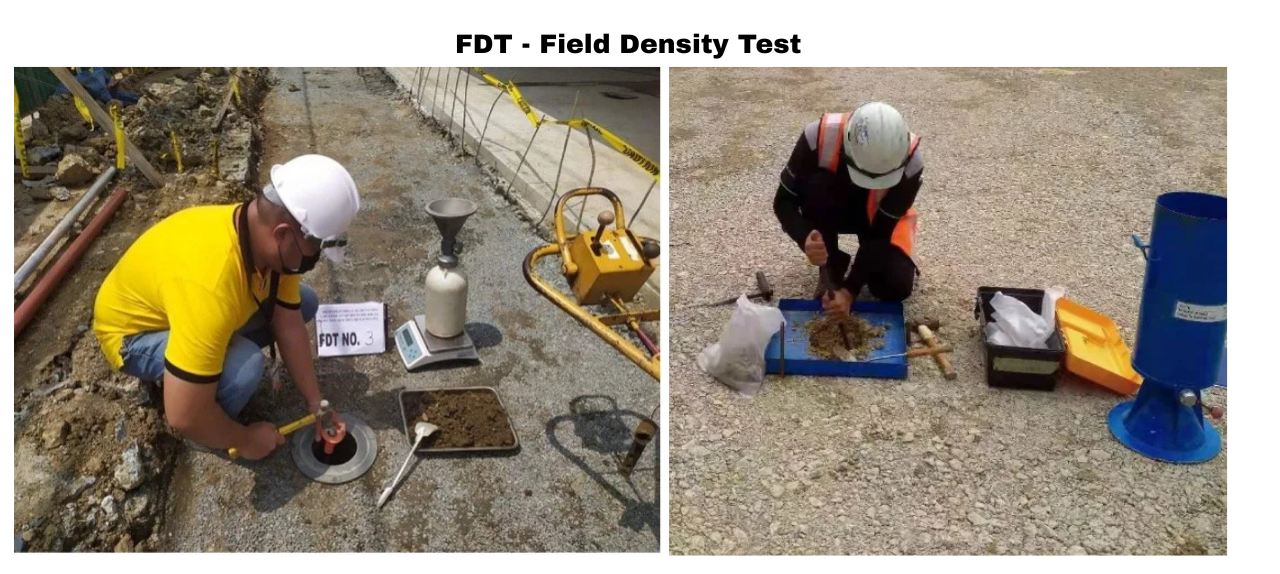
No completed fill layer shall be covered by the next layer until it has been tested, inspected and approved by the Engineer.
After completion of the middle level of the backfilling and compaction Field Density Tests (FDT) will be conducted on site, and the results will be submitted to the consultant for approval
For sloped areas, excavate benches to ensure horizontal deposition and uniform layering.
After completion of Final level of the backfilling & Compaction Field Density Test (FDT) will be contacted at site & results will submit to the consultant for the approval
4. Quality Control & Testing
Field density tests as per specification & Standards
Finished surface level will be followed as per approved drawings
5. Health, Safety & Environment
PPE to be worn at all times (helmets, vests, gloves, boots).
Safe access and egress to excavation areas.
Dust suppression and water management to protect the environment.
Machinery to be operated only by trained personnel.
Work Procedure For Concrete (Method Of Statement For Concrete Work)
Before starting any construction work, it is very important to prepare a work procedure or method statement. This document must be given to the consultant before the activity starts. The consultant will review it, and only after getting approval can the work start on site.
The steps below explain the procedure for doing concrete work, step by step.
Setting Out
Setting out will be carried out with reference to the established, approved survey points.
The Tolerance shall comply with Specification for Civil & Structural Works.
Ensure soil condition is ready to receive blinding.
Blinding Concrete
Fixed timber forms will be formed for edges of blinding concrete.
One-layer of 1000 gauge polythene sheet shall be laid prior to arrangement for blinding concrete.
All foundation shall have blinding concrete as per specification.
After final casting of blinding concrete Two coats of Approved bitumen paint applied in Horizontal surfaces & Two coats of approved bitumen paint & one layer of 6mm bituminous impregnated board applied over the paint surface. (As per Specification of Project)
Setting out and marking will be done over screed for starting shuttering & Reinforcement for footing.
All works shall comply with approved drawing & Project Specifications.
Form Work (Shuttering, Scaffolding)
All formworks shall be made from plywood used for the frame of formworks.
Formwork shall be sufficiently tight to prevent leakage of cement slurry while concreting.
Form work will be adequately propped, braced, and tied in position to ensure that it retains its shape and position before, during and after concreting.
Level guide shall be installed for the level maintenance of concrete.
Formwork will remain in place until the concrete has hardened sufficiently to resist damages from the removal operation which in this case in a minimum of 24 hours after placing of concrete.
The formwork will be removed in accordance with project specification; no form work shall be removed until the concrete has gained sufficient strength.
Formwork shall be coated with chloride free form release oil
Reinforcement fixing
Source of Reinforcement shall be approved by Consultant prior to us.
Fabrication & Deformation of steel will be done at Reinforcement steel fabrication shop at site.
Assembled reinforcement will be erected manually or using crane /suitable lifting equipment (If necessary).
Clear cover to all reinforcement shall be provided as per approved drawing & Project Specifications.
default
Electrical & Plumbing Conduits installation
Make sure that all electrical, Air conditioner & Plumbing sleeves completed as per construction drawings & Project specification & approved by consultant.
Get the MEP clearance signature form the MEP Team Prior to concrete works
Casting of concrete
inspection from consultant & QA QC will be done Prior to concrete works
Concrete will be delivered comply with design ready-mix, the max time between mixing and placing concrete shall not exceed 90 min.
Concrete pouring shall be scheduled such that concreting will not take place at mid-day (10:00am to 5:00pm) during hot weather period and when shade temperature exceeds 40ºC.
Concrete will be placed as nearly as practicable to its final position and care taken to avoid segregation of concrete, displacement of reinforcement, formwork or embedded Items, maximum free fall for concrete shall not exceed 1.5m. Temperature of concrete at the time of placement shall be measured and recorded each pour card.
Prior to pouring of concrete, delivery tickets shall be checked and verified the grades, mix no, time, temperatures, slump, and sample cubes.
Immersion vibrator shall be used to ensure that concrete is worked around the Reinforcement, around embedded material and into corners of forms to eliminate all air or stone pockets which may cause any cavity.
Anchor bolts shall be placed as indicated in drawings, using suitable template, and firmly secured to the formwork
Vibrator: sufficient quantity with adapted size shall be used.
Concrete repair shall start immediately after formwork removing.
Prior to pouring of concrete, rebar inside from work shall be cleaned (free of dust) by air blowing.
NO concrete repair shall be carried out without consultant approval and for major repairs like honey combing etc.
Curing the concrete
Surface of hardened Concrete Shall be covered with Hessian cloth plus polyethylene sheet to prevent evaporation, to retain the moisture with subject to continuous water curing for minimum 7 days after placing of concrete.
The side forms shall be cracked after 24 hours to get initial water to the surface.
Construction joints shall be cleaned for any spilled concrete and shall be covered with Wet hessian which will be kept damp.
All construction joints shall have continuous key at center of joint. bonding agent shall be applied before commencing successive concreting.
Curing the horizontal surface shall be immediately after placing the concrete and shall comply.
The purpose of this Method Statement is to establish the rules & Safety requirements to be applied during the Excavation, Works are properly executed in accordance with Project Specifications and applicable standards.
2. Responsibilities of Project Team
2.1 Project Manager
Responsible for the project objectives by managing cost, time, scope, quality, and ensuring all project documentation, quality, and safety procedures are up to date and accessible.
2.2 Project Engineer / Civil Engineer
Responsible for overseeing all construction activities, also to make sure that all activities are followed by Project approved drawing, method of statement & Specification
2.3 Construction Supervisor / Foreman:
Responsible for ensuring work execution managing permits, conducting toolbox and enforcing safety measures and Find out the work executed by skilled labor or Technicians
2.4 Civil QC Inspector (QA/QC):
Responsible for inspecting all required activities before & After, following the inspection records.
2.5 Safety Officer:
Responsible for implementing safety compliance, conducting toolbox talks, making the proper barricading and signage, and immediately stopping and reporting any unsafe acts or conditions.
Safety officer will Follow the All HSE Requirement
Make sure that all labor and working staff used Proper PPE
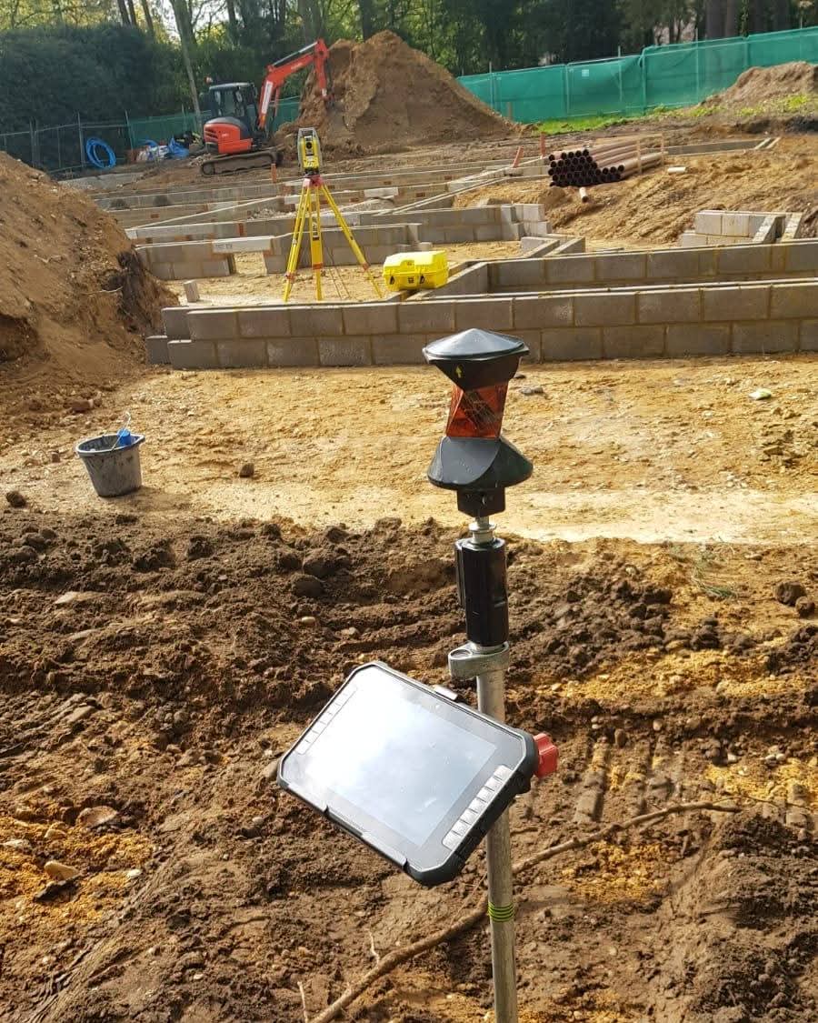
3. Surveyor
To verify the survey instruments working in good conditions and it has the valid certificates before stating the work
Study the drawings thoroughly and make ensure all the drawings are approved by Project Team & Consultant.
Check the pipeline routes and all road crossing shall be followed by Govt Approved benchmark
Before start the survey works check any obstacles from existing underground utilities.
Tripods shall be checked prior to fix survey instruments. And always handle the instrument with safe method and keep in good condition.
To perform the survey, work as described method statements and approved procedures.
Control points shall be checked periodically from Consultant Reference points to ensure control points are not disturbed.
If any changes of values or coordinates variations arises inform to civil engineer / manager.
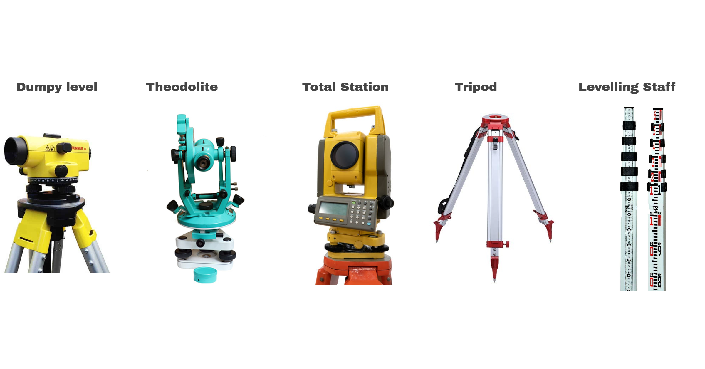
4. Required Equipment
Levelling Instrument’s Such as (Dumpy level or Theodolite or Total Station), Tripod, Levelling Staff
Excavator Machineries – Excavator, telescopic Handler etc.
Hand Tools – shovels, picks, and axes etc.
Safety Tools – Fire Extinguisher, Fire Blanket etc.
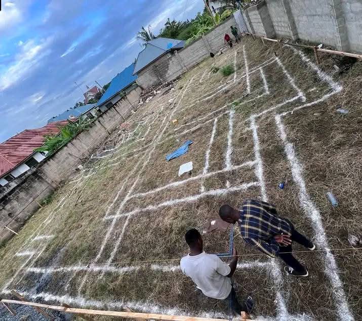
5. Survey & Marking
Check the ground levels with a survey to understand the current height.
Draw lines to show where excavation should happen, based on approved plans.
Check for any underground cables or pipes using special equipment.
Mark reference points to guide the depth and position of excavation.
6. Site Preparation
Mark the area to be dug using white chalk or lime powder.
Put up safety signs and fences around the site.
7. Excavation Process
Start excavation using the required machineries.
For deep holes, excavate in layer by layer
Excavate to the required depth as per approved drawings.
If water collects in the hole, use a pump to remove it.
Move the excavated soil to the approved dumping area
8. Inspection and Verification
A surveyor checks the depth and position of the excavation.
An engineer checks that the excavated levels & sizes are as per drawings.
QA / QC wil prepare the inspection report & Submit to the consultant approval.
Consultant will check the site Inspection will be approved by consultant prior to start next activity.
If any comments while site visit from consultant will be notified in the Inspection report accordingly that needs to be rectify.
The inspection report will be documented & Maintain for future purpose
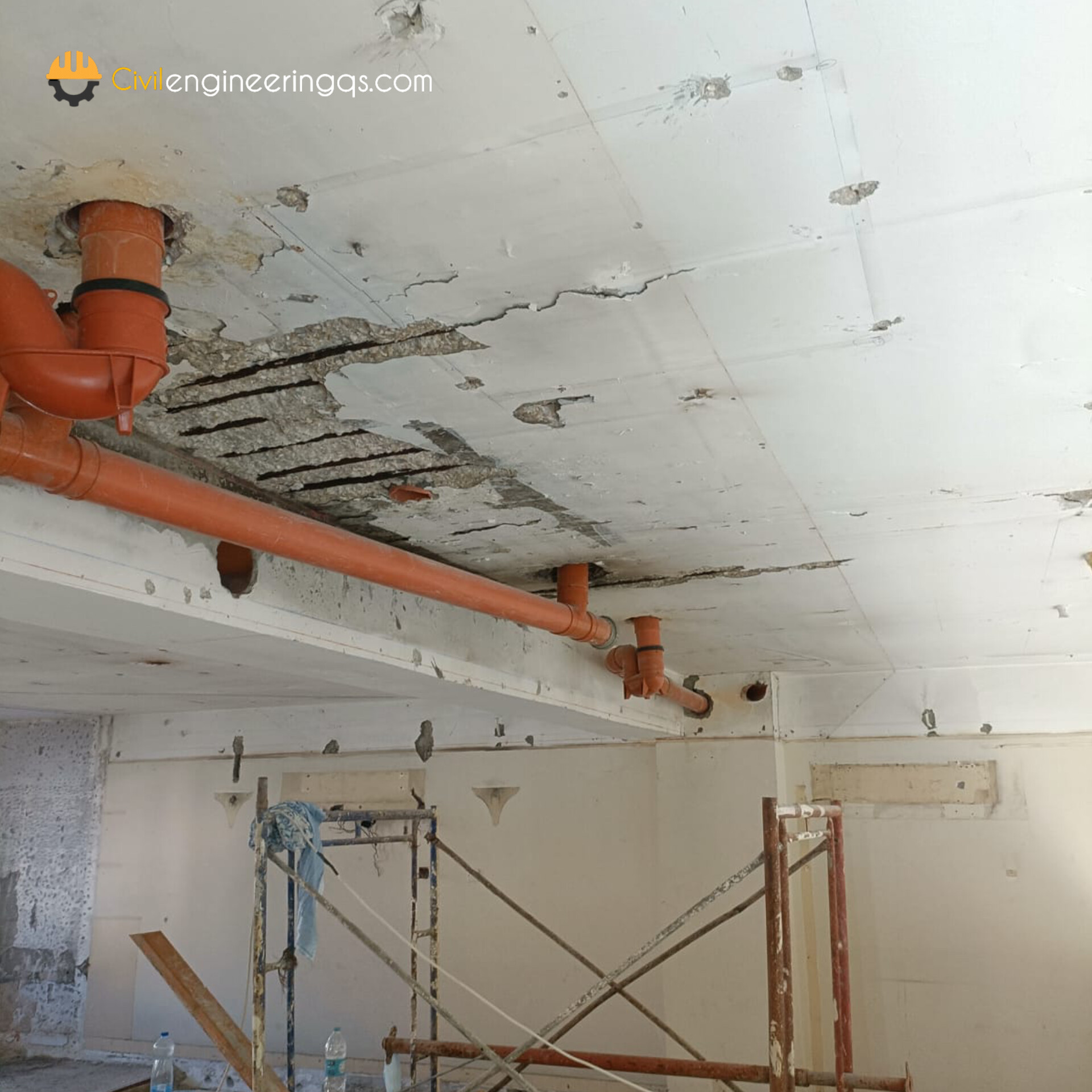
Concrete repair is the process of rectifying damaged concrete areas, usually these damages can happen if various factors such as water, corrosion, physical impact or some other factor. so , its should be necessary repaired at on time otherwise theses corrosion or damages will continue spread to other areas. Following steps are involved in concrete repair work.
Process of concrete Repair
Inspection & Identification of Defective Areas
Surface Preparation & Necessary arrangement
Chipping the old concrete in defected areas
Steel preparation and Anti-corrosion coating on steel
Steel Anchoring
Shotcrete
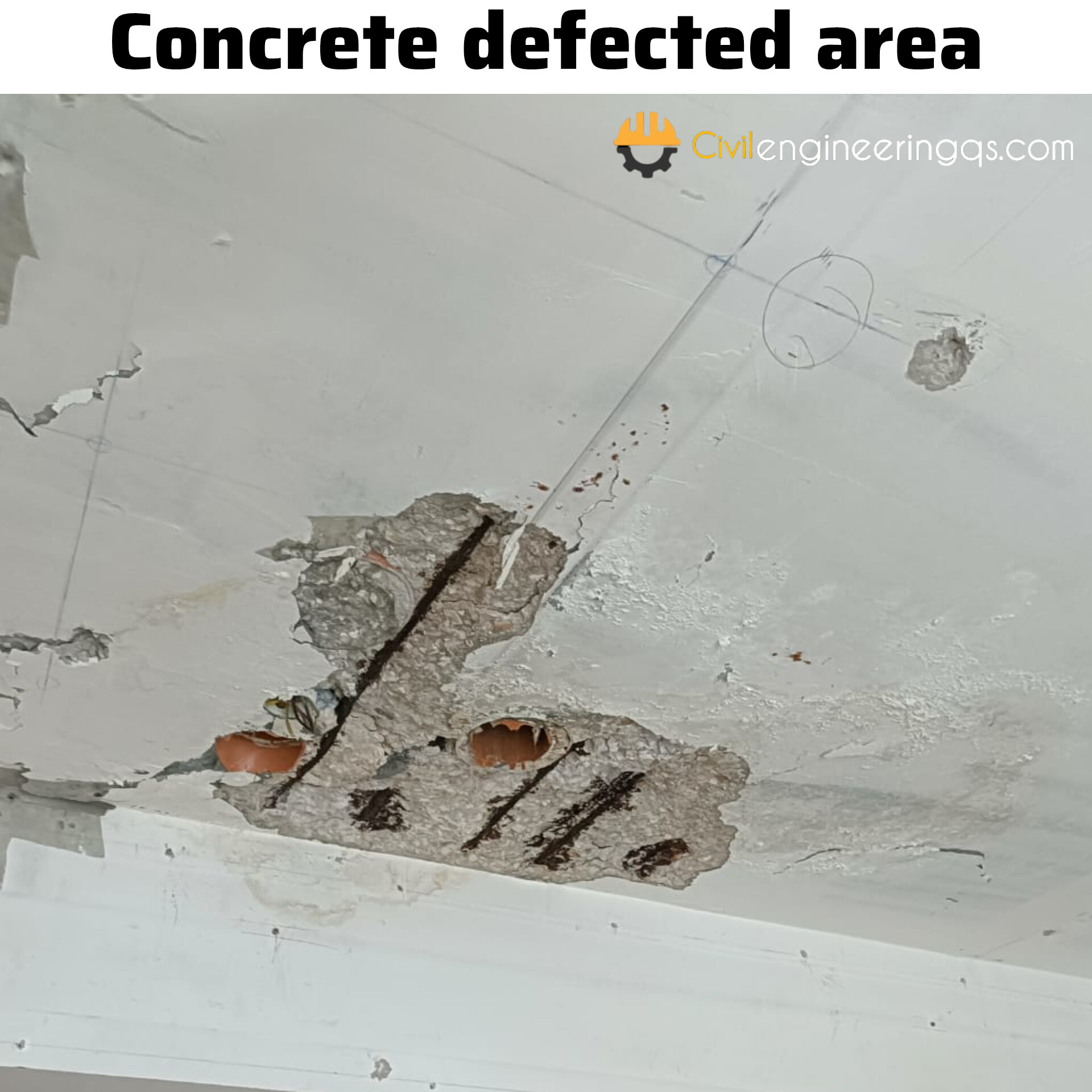
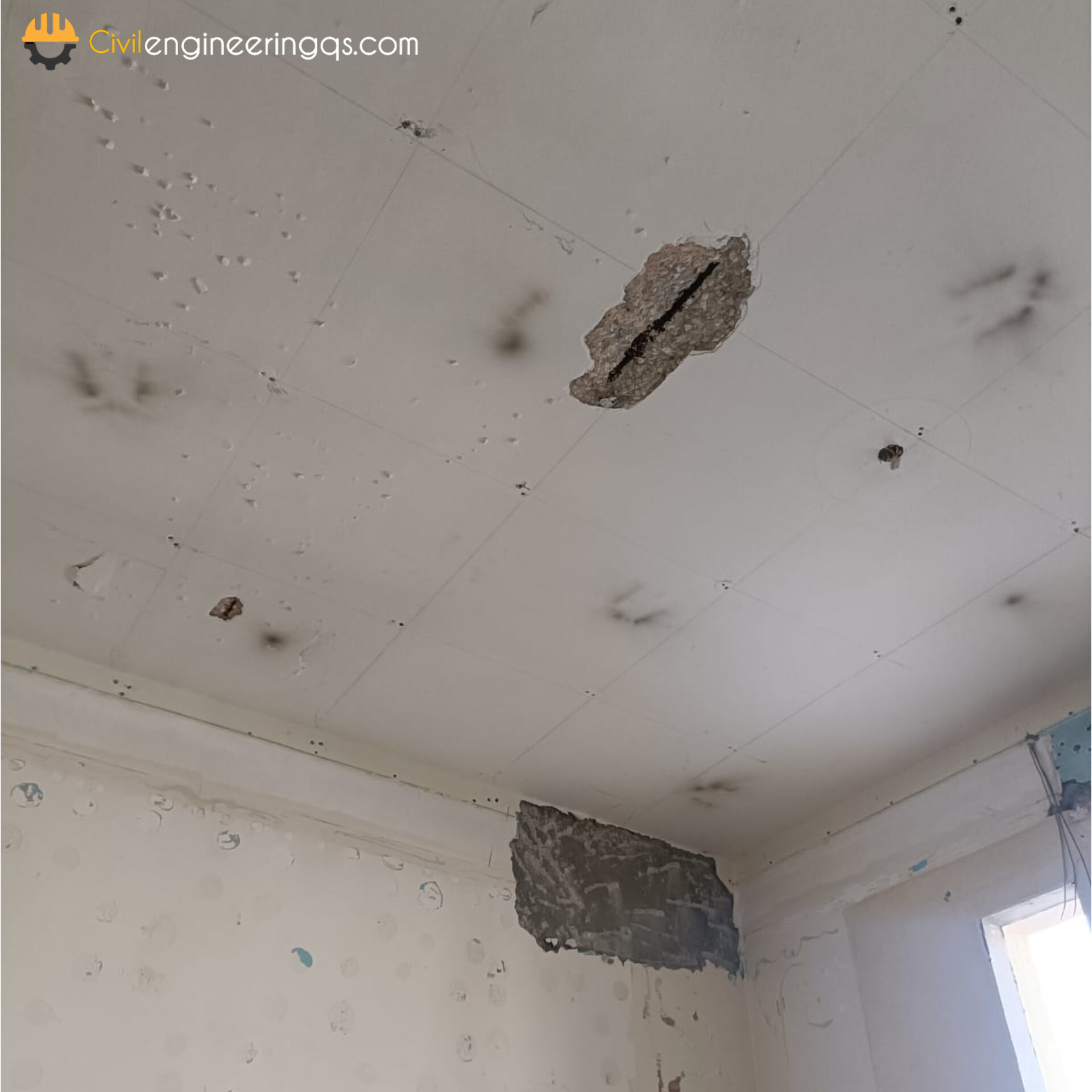
1. Inspection & Identification of Defective Areas
Conduct an visual inspection of the concrete structure to identify visible cracks, corrosion, sapling, or other signs of damage.
If needed make an required test like Non-Destructive Testing to identify the defected areas
2. Surface Preparation & Necessary arrangement
Mark an defected areas prior to chipping
Arrange an necessary arrangements such as Safety, scaffolding, required tools and machineries.
Clean the surface and remove the dust prior to chipping work
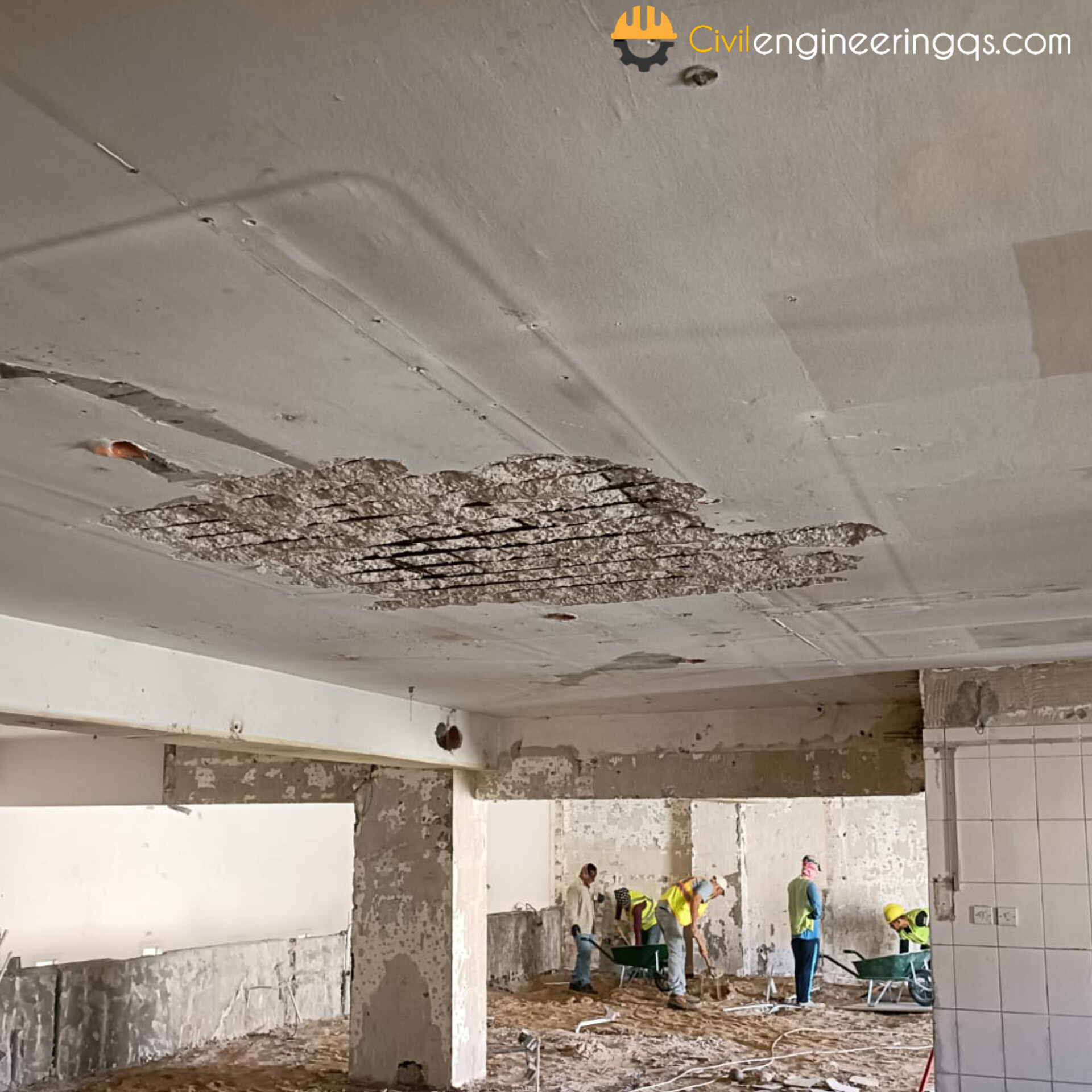
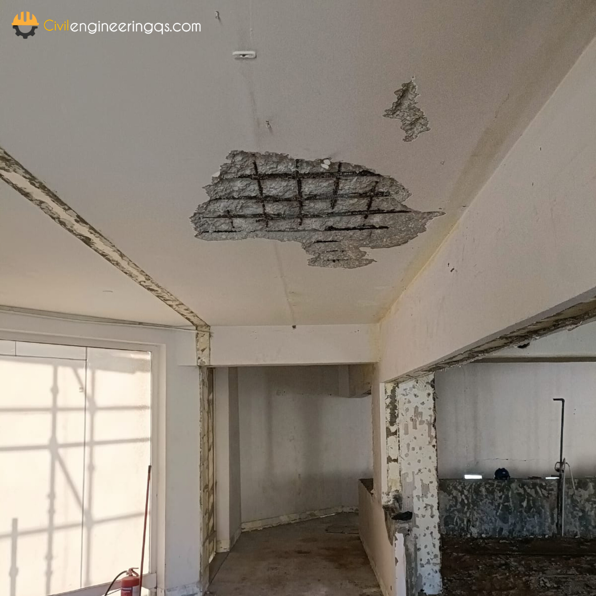
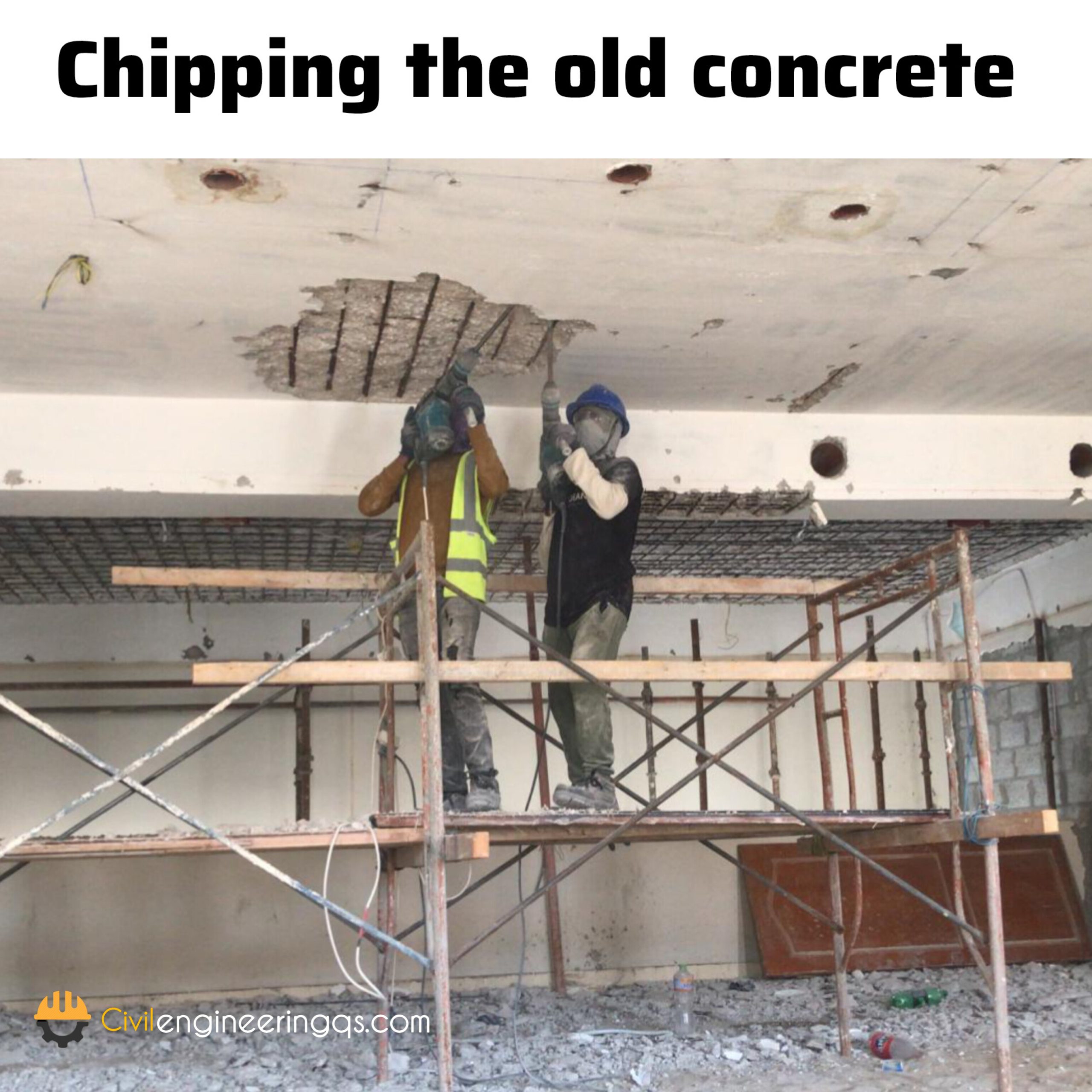
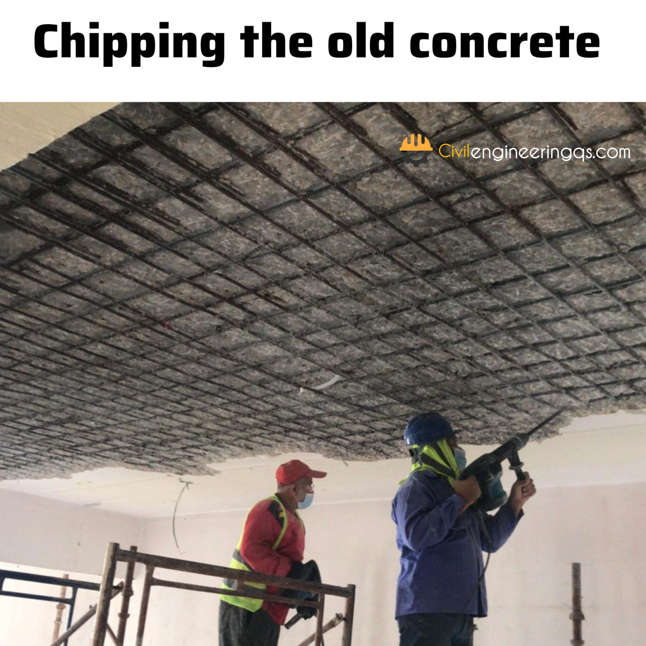
3. Chipping the old concrete in defected areas
Setting-Out, Alignment, Verticality, Elevation, and required rebar’s anchoring locations & spacing shall be in accordance as per project specification.
Concrete chipping of the Columns & ceiling & other vertical structures and Floor surface will be carried out using jack hammers, drilling tools & breakers to achieve a good bond between old and new concrete as per required thickness and to remove all the segregated, damaged, or deteriorated concrete until a sound homogeneous substrate has been reached.
After chipping the concrete The Surface should be rough and properly cleaned using compressed air to remove loose / chipped materials.
The surface should be cleaned from dust, oil, grease, corrosion deposits, or any other containments that could impair the adhesion of the repair mortar.
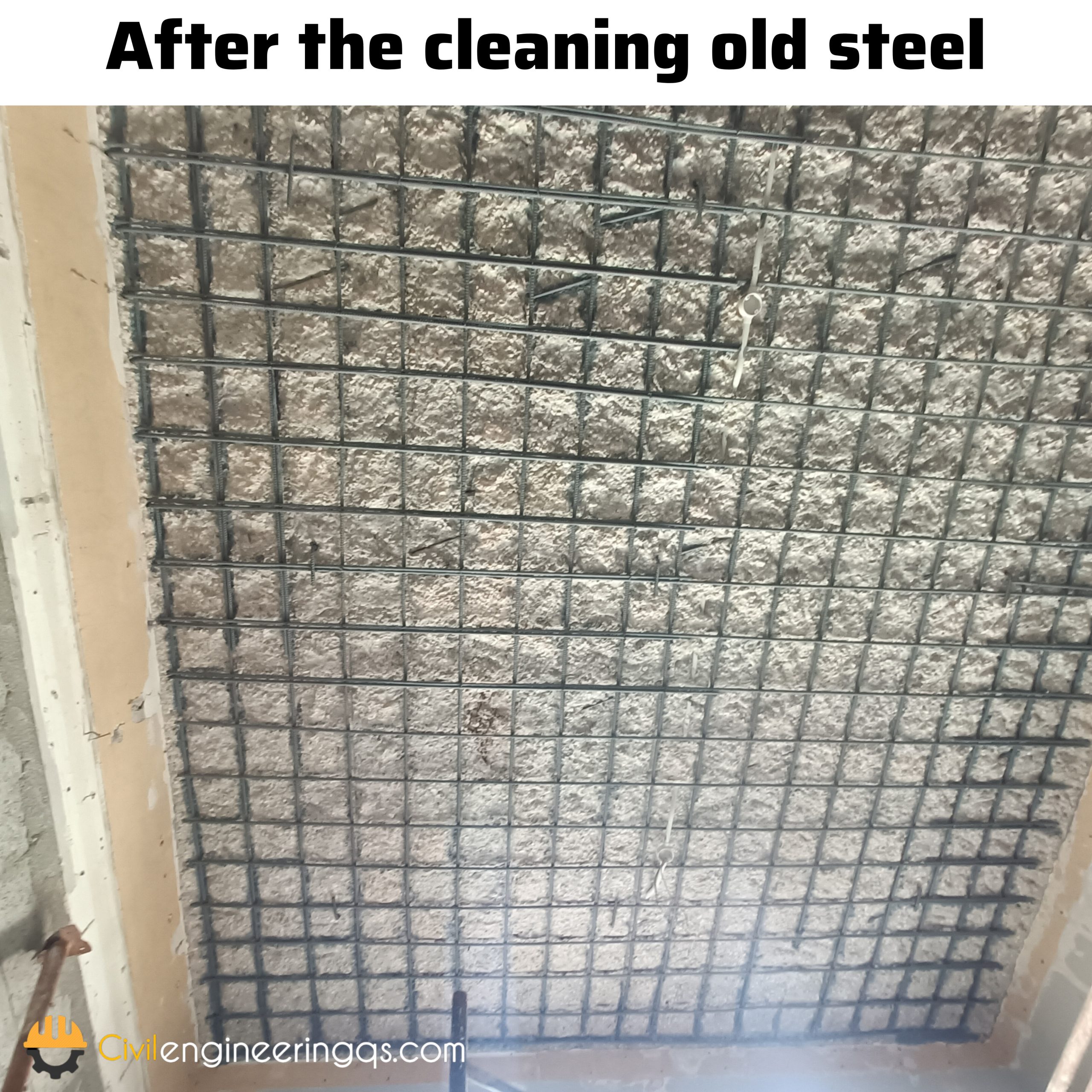
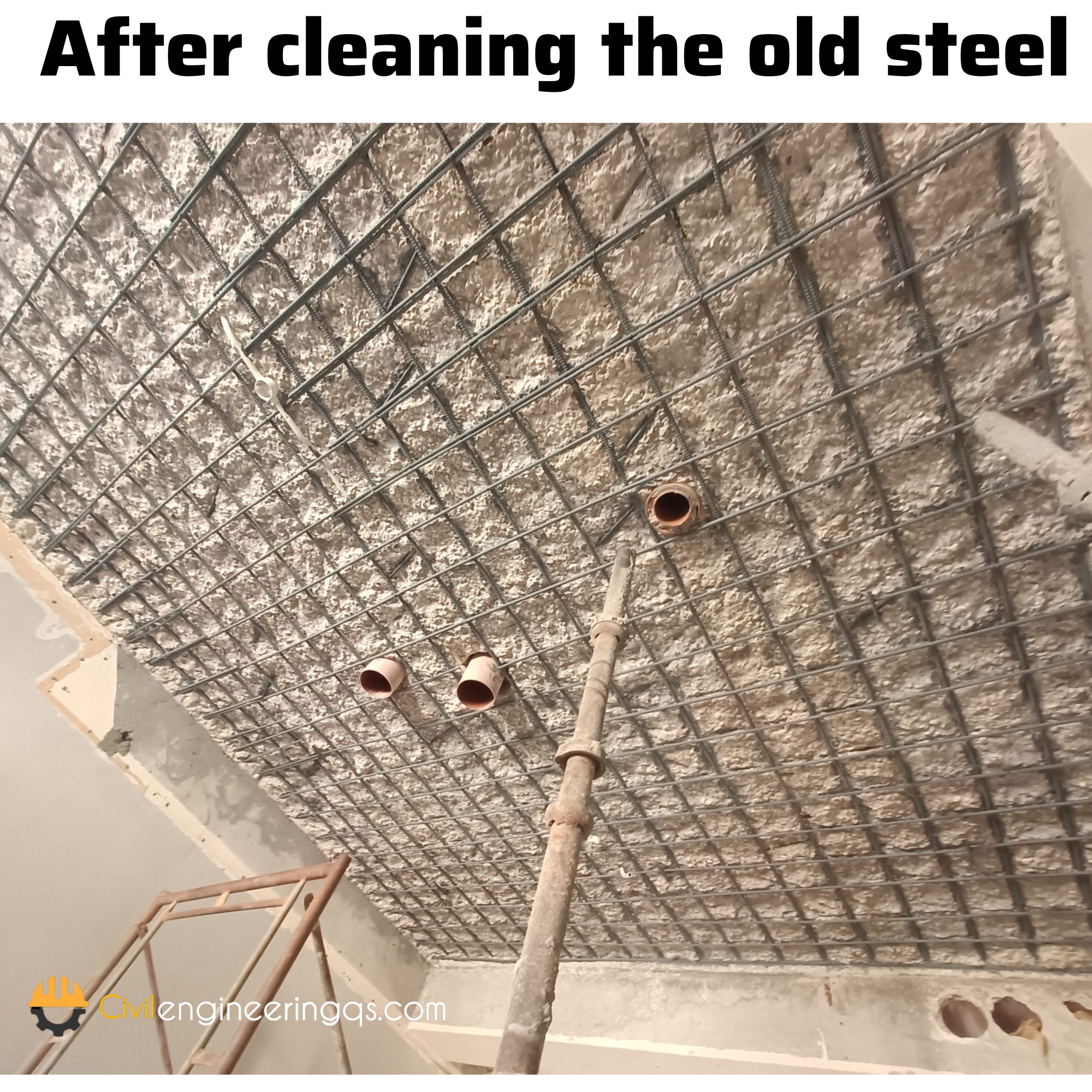
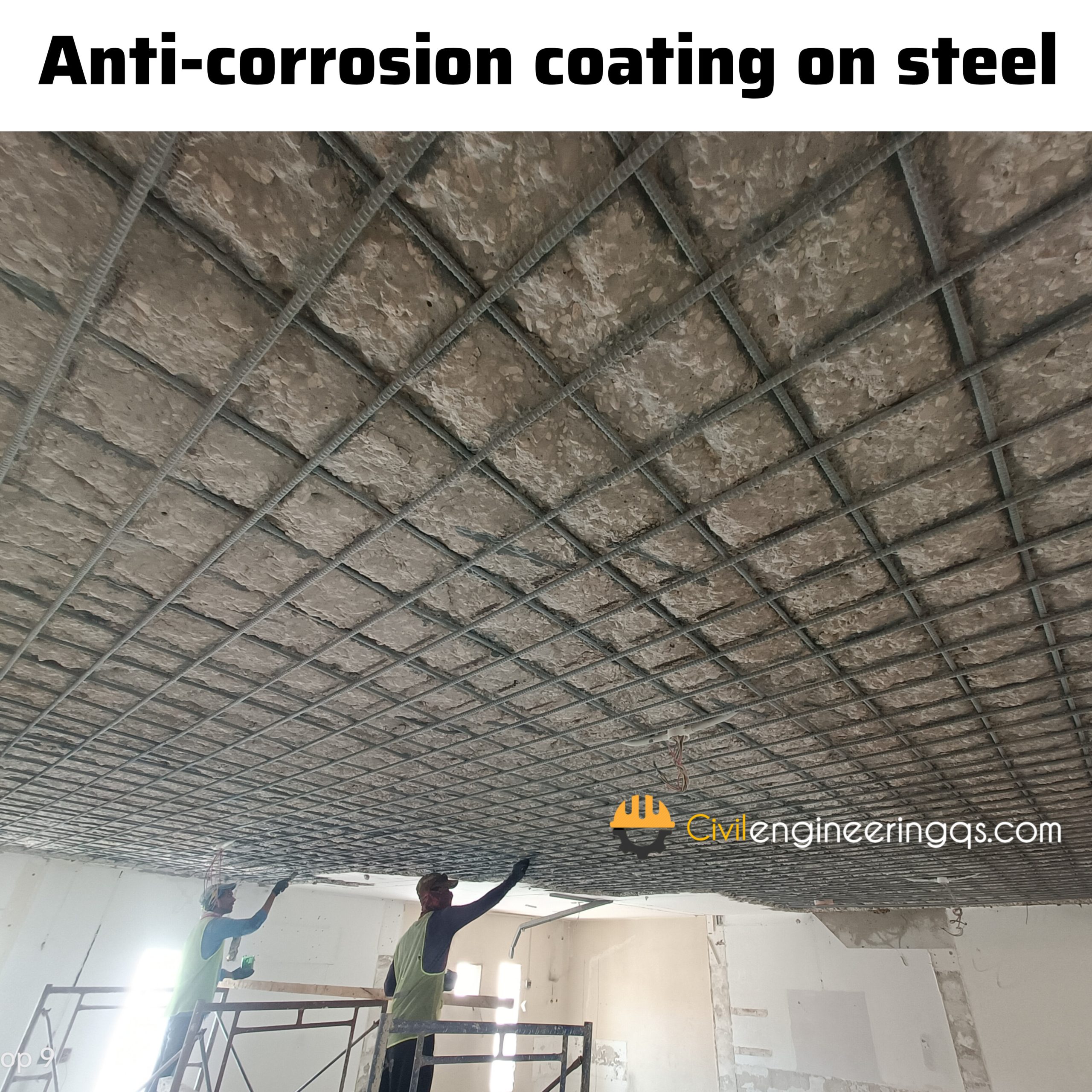
4. Steel preparation and Anti-corrosion coating on steel
Break along corroded steel bars in the repair area until the non-corroded bright steel observed, it may necessary to break out the concrete beyond original repair area in order to achieve
If the defected areas are big, clean the reinforcement steel using an sand blasting technique.
If the defected areas are small, clean reinforcement steel using an steel brush
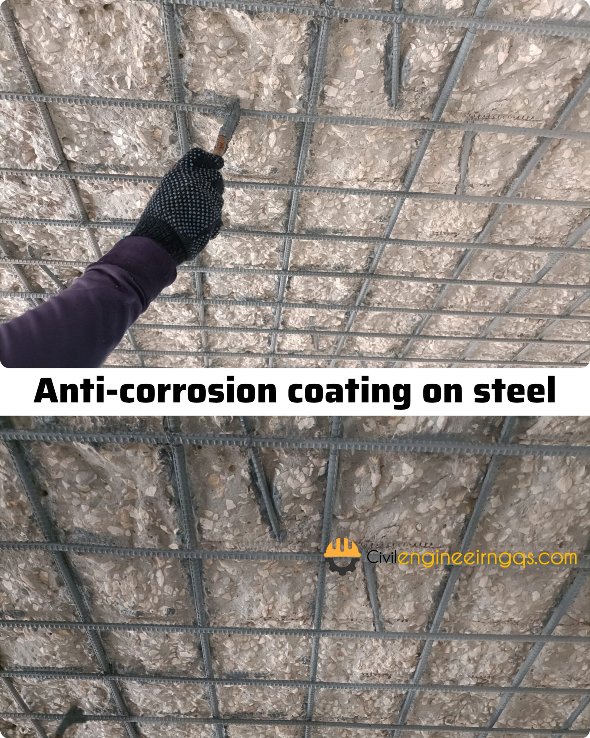
All cleaned steel reinforcement should be primed with (Anti-corrosion) zinc-rich epoxy coating
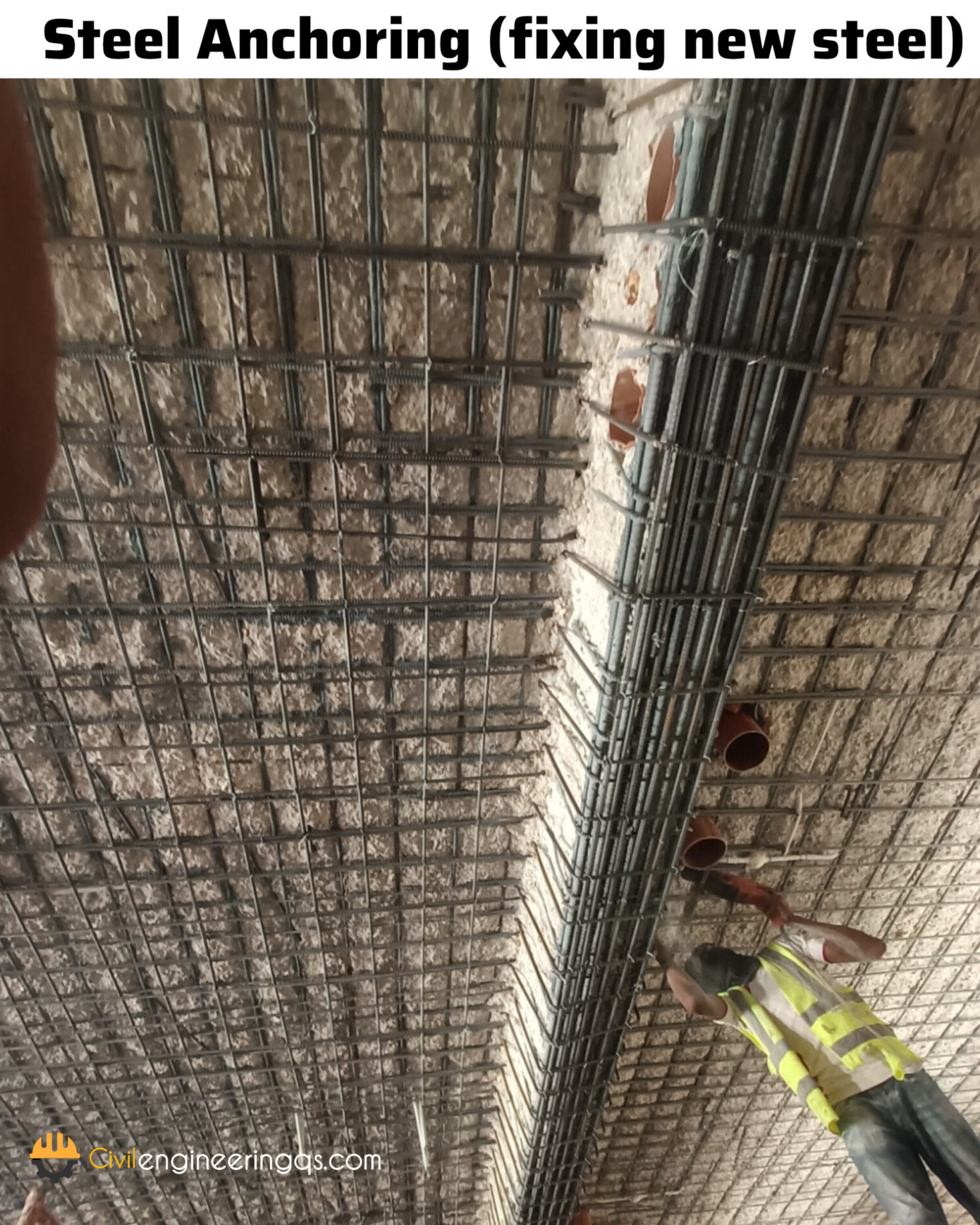
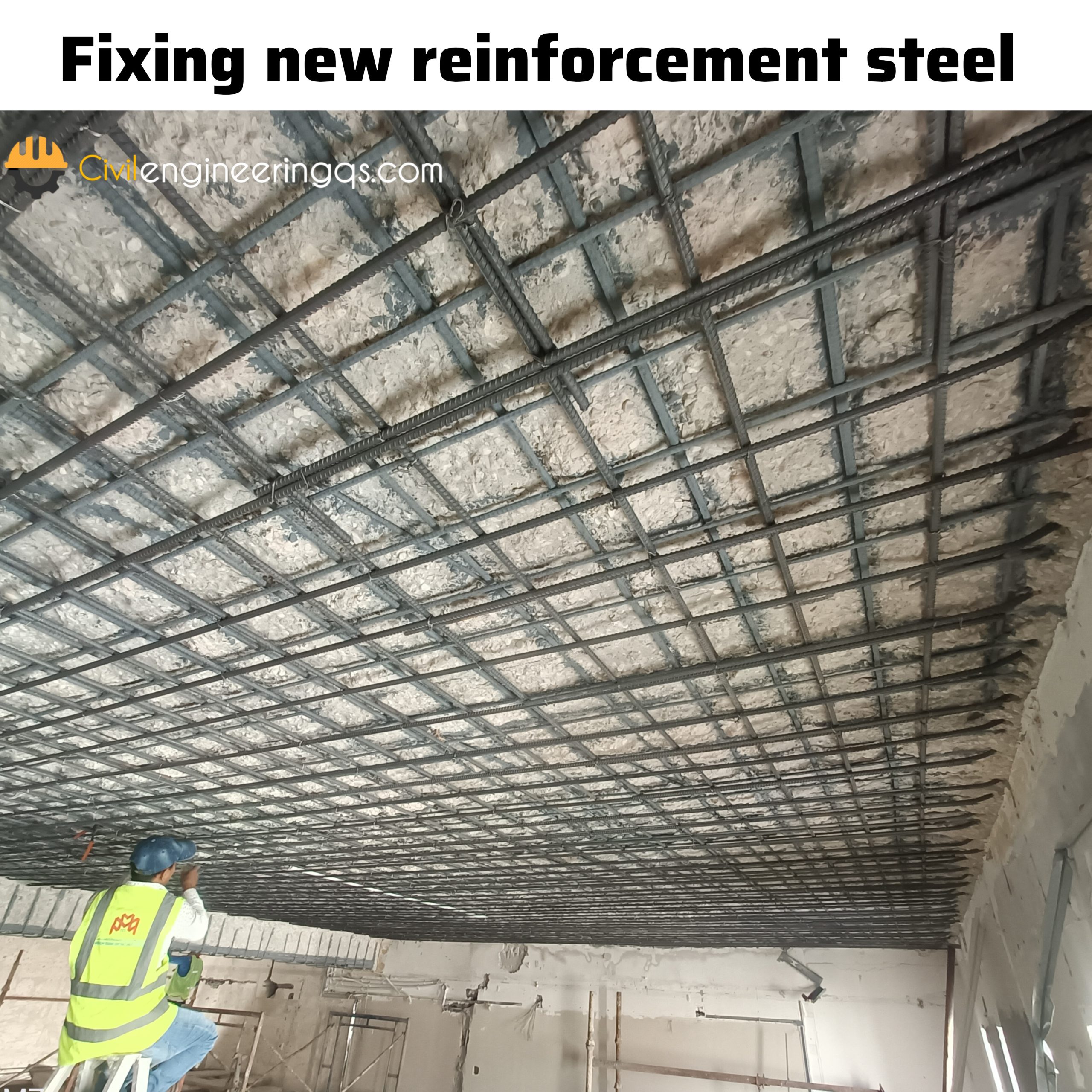
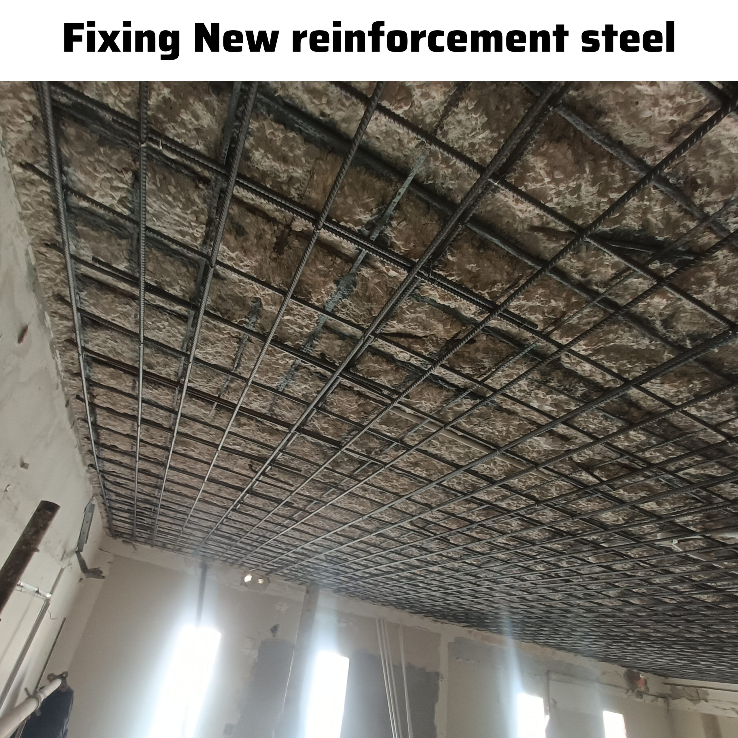
5. Steel Anchoring
Rebar anchoring installation carried out should be as per approved location and properly fixed and inspected by the consultant prior for additional rebar installation.
Drilled holes are filled with epoxy or grout before anchoring the new reinforcement steel bar.
Install the required reinforcement rebar as per approved structural drawing.
Ensure all required rebar spacing, lapping, covering shall be carried out as per approved drawings.
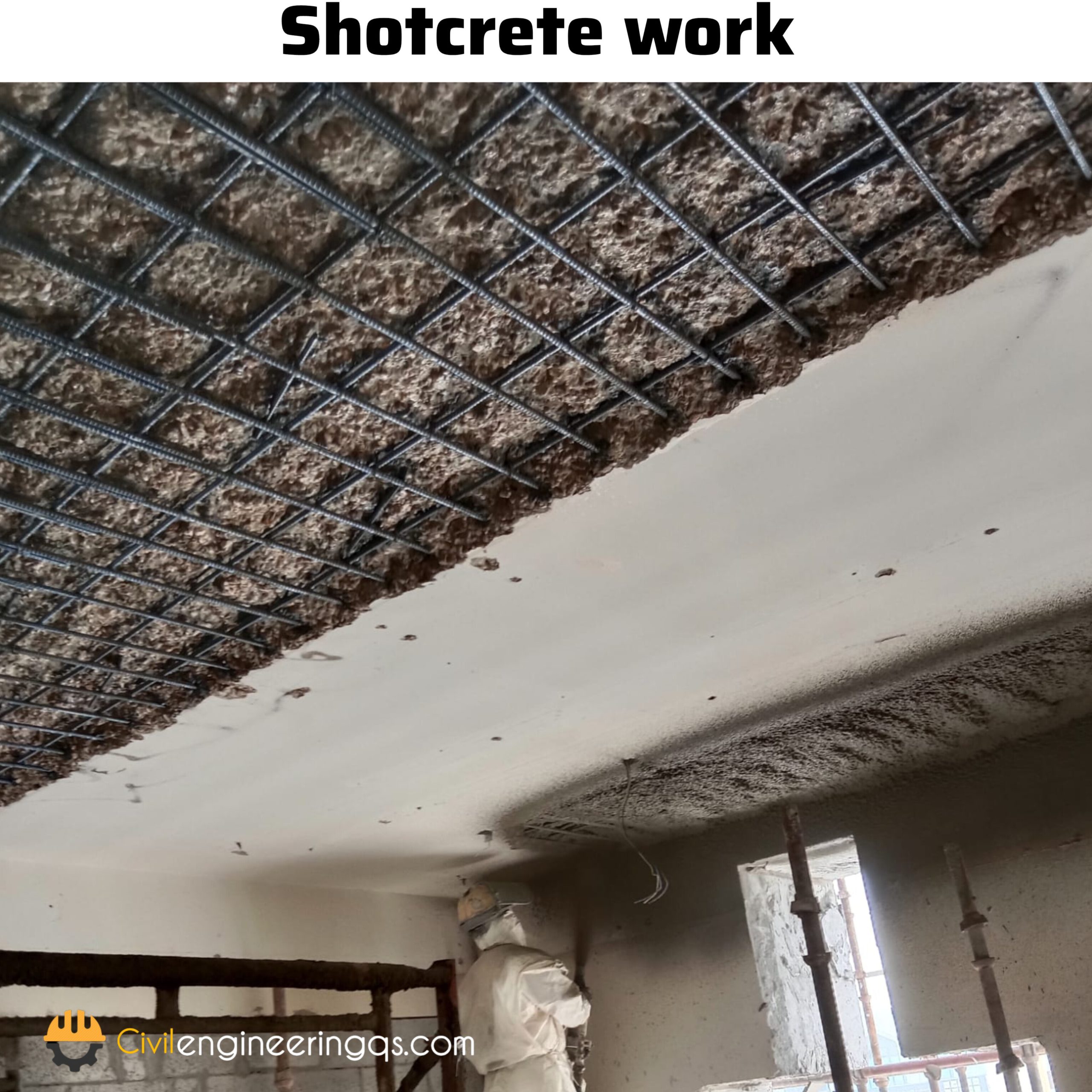
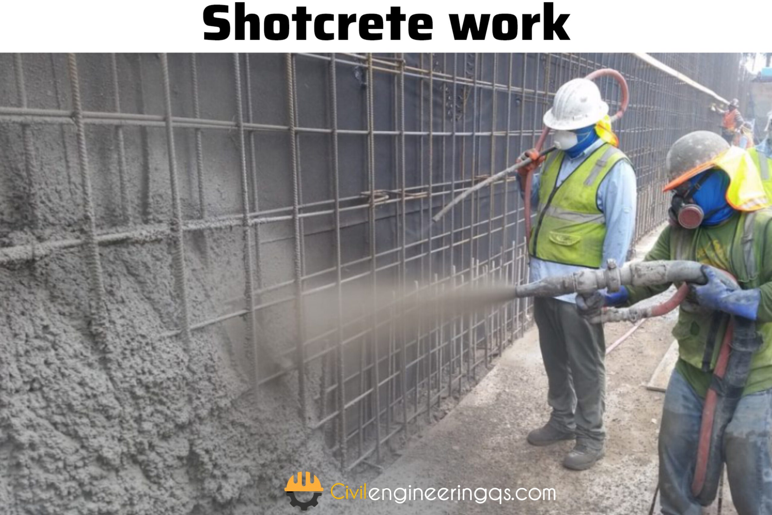
6. Shotcrete
Prepare an levelling & make an curing before applying the shotcrete
Prepare the shotcrete mixture as per project specified mix design.
Apply the bonding agent on steel before applying the shotcrete used for good adhesion between the new shotcrete layer and the existing concrete.
Apply shotcrete (sprayed concrete) using a high-pressure hose to the prepared surface. This can be done in layers, ensuring even coverage and proper compaction
Finishing: Make an good finish on the shotcrete surface using trowels and other required tools.
Continue curing for 7 to 28 days to ensure the concrete reaches its full strength
Method Statement for Repairing Cracked Areas with Plaster
On the construction projects before starting the activity of crack repair must to submit the method of statement to the consultant for their approval, consultant will check our procedure of work and return to us with the comments if needed. So, once our method of statement is approved, we can start the work at site. The following post will describe you that Method of statement of cracked areas repair with plaster, its involved in following steps.
Identify the cracks & Preparing Necessary arrangements
Removal of Damaged Plaster
Application of steel wire mesh
Application of Rush Coat with cement and sand mortar
Application of New Plaster
Quality Assurance
1. Identify the cracks & Preparing Necessary arrangements
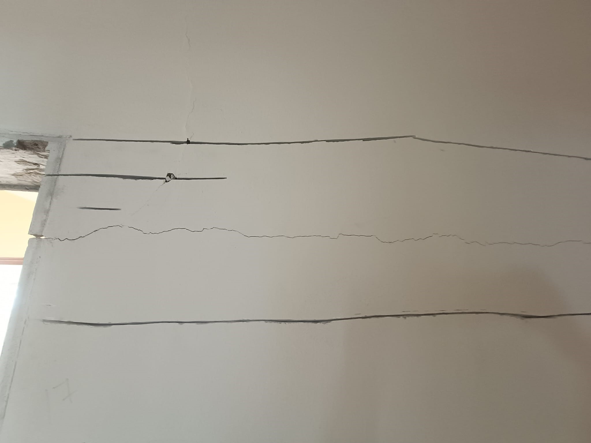
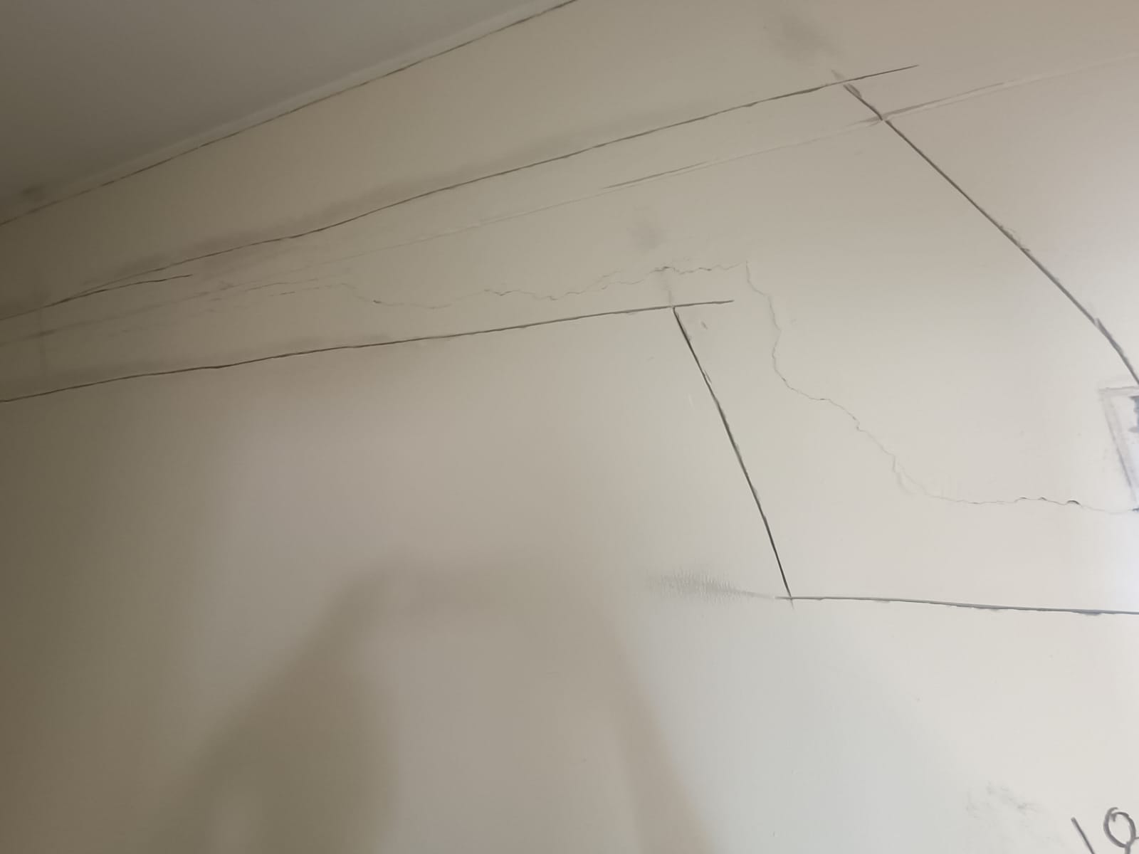
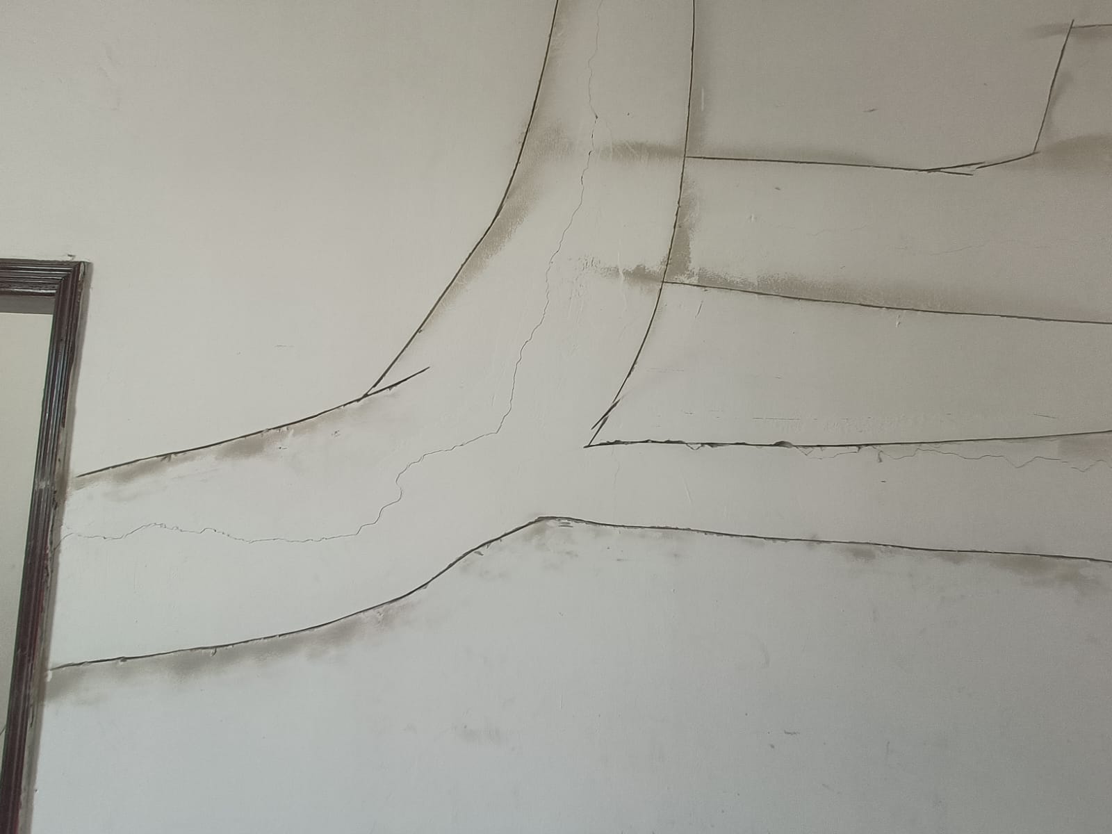
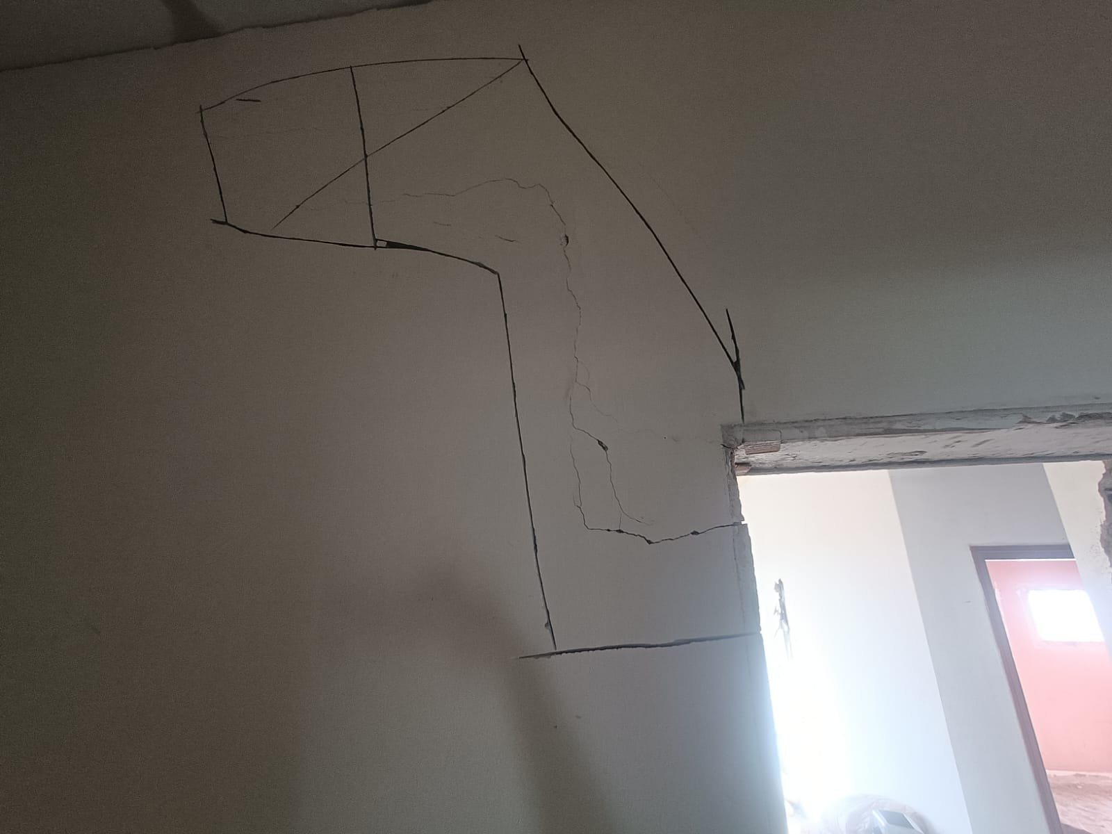
Identify and mark the areas of cracks on the existing plaster.
Prepare the necessary arrangements such as scaffolding, required tools and machineries etc.…
Clean the exposed area thoroughly with a brush to remove dust and debris. The Following Images shows the plaster crack areas
2. Removal of Damaged Plaster
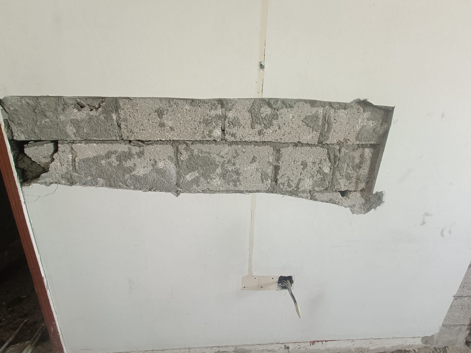
Use a required tool or machine and carefully remove the damaged plaster from the identified crack areas.
Cut the plaster from cracks, cutting must to be 10cm from each side from the crack
Make sure all damages crack area plasters removed properly
Also make sure that the surrounding plaster remains not damaged.
Check the Plaster removal surrounding area, if any week point.
If any week point founded will remove the plaster from that areas also.
Remove the wastages (old plaster) from the working point. The Following Image after removal plaster form the crack
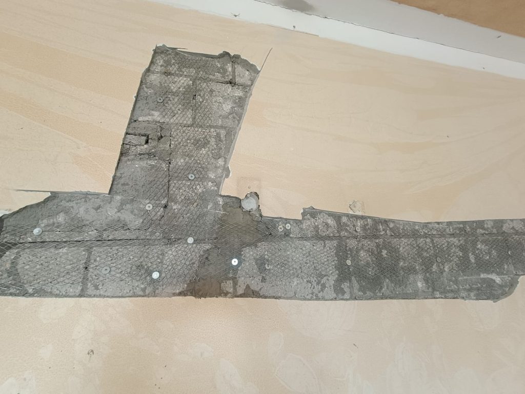
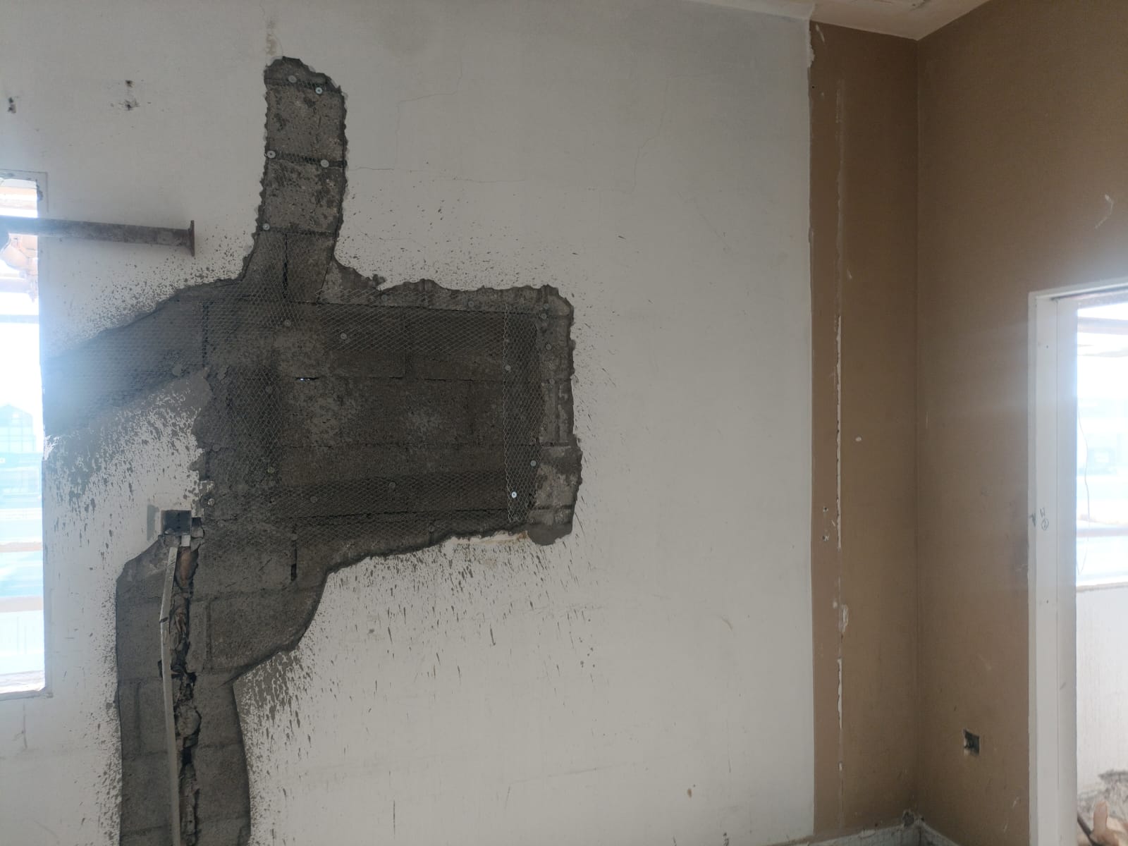
3. Application of steel wire mesh
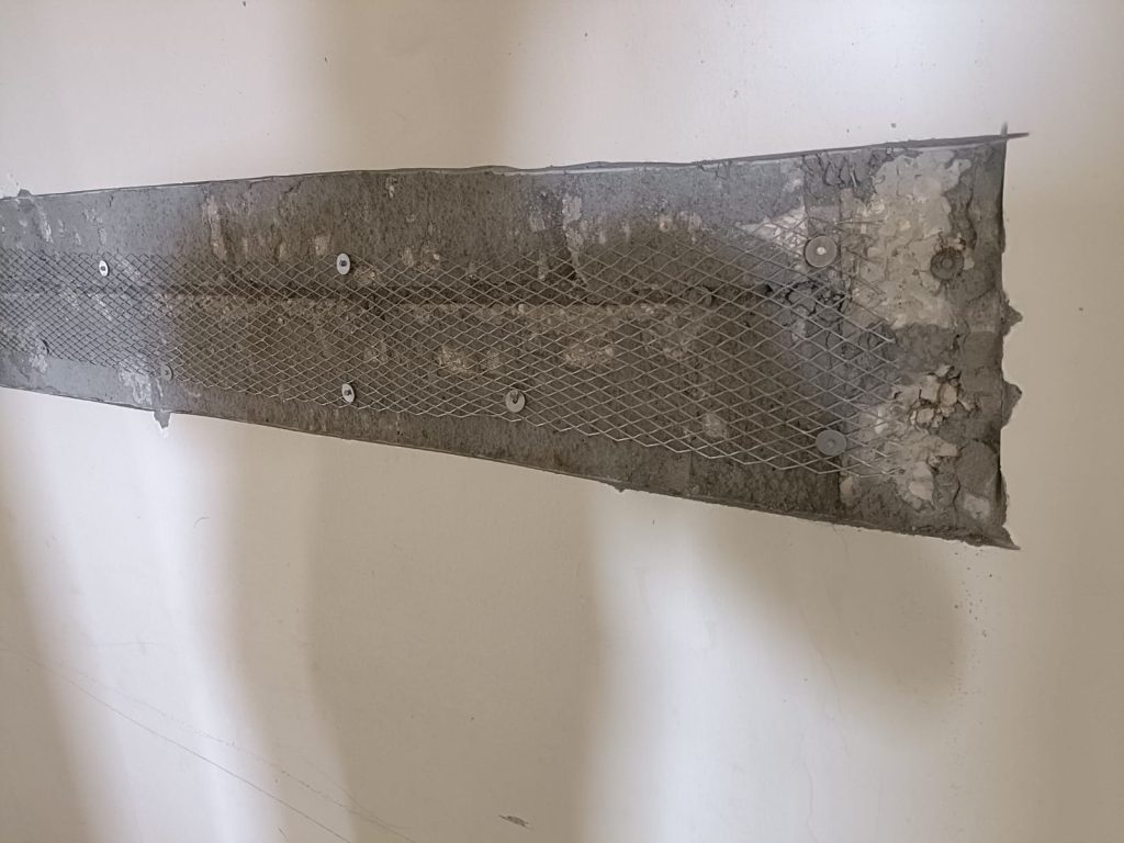
Cut the steel wire mesh required size and fit the required area
Place the Steel wire mesh over the cracked area, make sure that proper adhesion and coverage.
Make sure that mesh provided with sufficient overlap from the joints from each side. The Following Image after Applying of Steel wire mesh
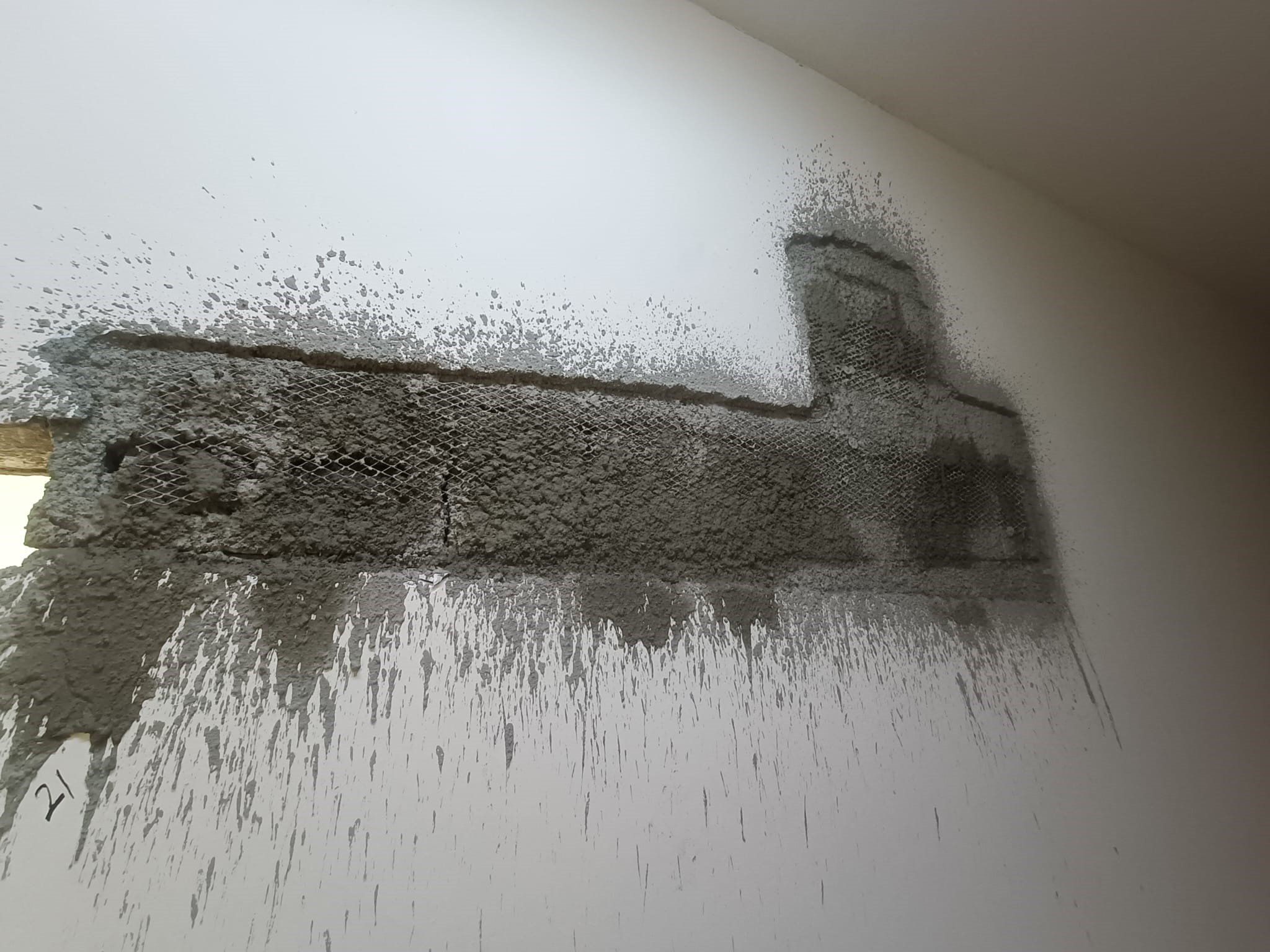
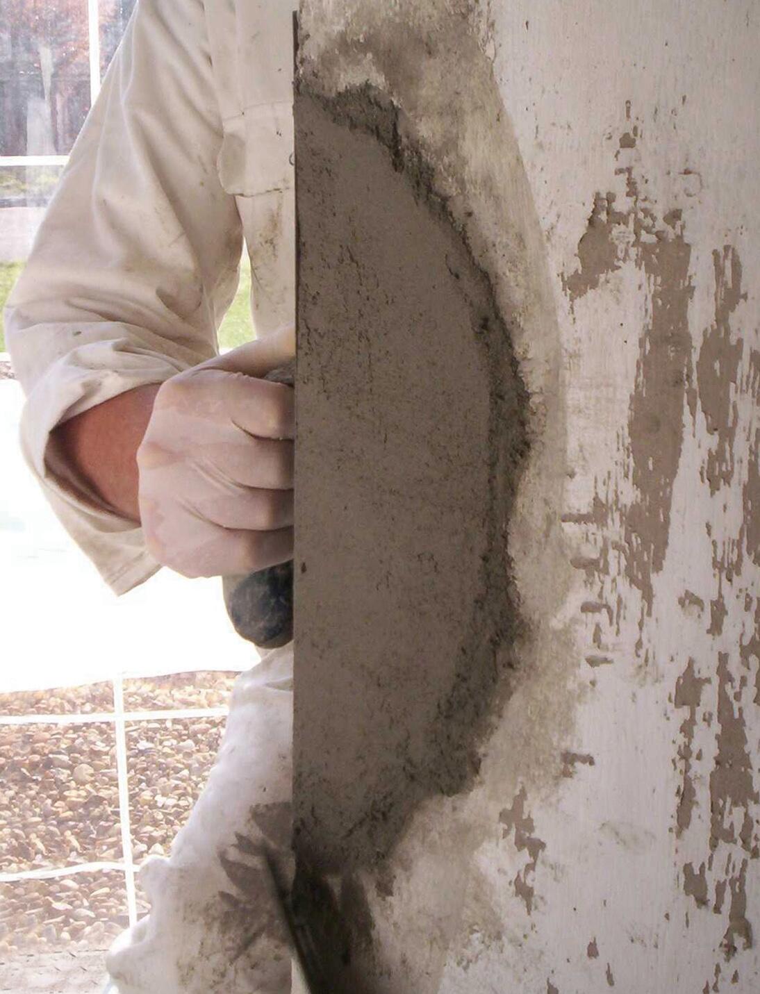
4. Application of Rush Coat with cement and sand mortar
Prepare the rush coat mixture according to manufacturer instructions or project specification.
Make sure the proper ratio of bonding agent to plaster.
Apply the rush coat evenly over the plaster mesh, ensuring full coverage and smooth application.
Allow the rush coat to dry completely before proceeding to the new plaster The Following Image after Applying rush coat with cement sand mortar with bonding agent
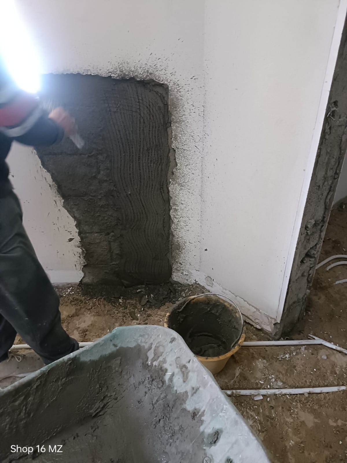
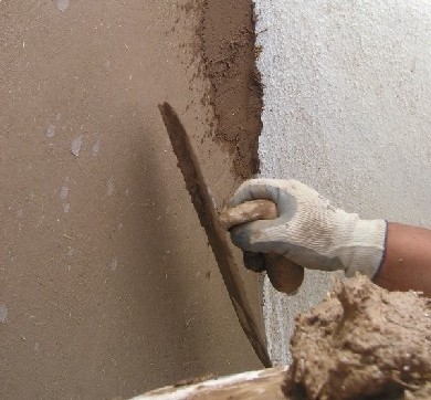
5. Application of New Plaster
Prepare the new plaster mix as per project specification.
Apply the new plaster over the rush coat, layer by layer as necessary to achieve the required thickness.
Use trowels or necessary tools to make smooth and good finishing surface.
Use levels and make sure that plaster applied evenly without any undulations.
Allow the new plaster to dry completely before finishing or painting, if required.
6. Quality Assurance & Safety
inspect the repaired areas and check that the work has done with the high-quality standards with project specifications.
Address the defected areas and make sure that rework done properly.
Prepare the final inspection to conform that all repair works completed properly with project specification.
Make sure that all workers wear the safety requirements such as safety shoe, helmet & mask etc.…
Also check properly working at heights or on scaffolding, that safety barriers and signs are in place to avoid accidents.